
- Home
- Brand
- Connectivity
- 3.5mm Line (4)
- 3g-sdi (6)
- Bluetooth (15)
- Bluetooth, Wireless (15)
- Digital Rf Wireless (9)
- Hdmi (9)
- Infrared Wireless (8)
- Mini-xlr (5)
- Sdi (3)
- Tbd (29)
- Uhf (16)
- Uhf, Wireless (11)
- Wired (10)
- Wireless (800)
- Wireless Xlr (10)
- Wireless, (5)
- Wireless, Bluetooth (8)
- Wireless, Fm (6)
- Wireless, Xlr 3 Pin (13)
- Xlr 3 Pin (4)
- ... (4355)
- Item Weight
- Maximum Spl
- Model
- 3pv (17)
- 512–542 Mhz (8)
- Adapter (10)
- Blx14 / Pga31 (22)
- Blx24 / Sm58 (14)
- Blx288 / B58 (9)
- Blx288 / Beta58a (17)
- Blx288 / Pg58 (10)
- Dmx512 (13)
- Dx5 (19)
- Ft11 (11)
- Ft11+pr13 (11)
- Mars 400s (11)
- Mars 400s Pro (11)
- Rode Wireless Go (16)
- Spm6775 (8)
- Swift 800 (8)
- T130-t131 (8)
- Ucr411a (8)
- Wpm-200 (41)
- ... (5069)
- Type
- Adapter (27)
- Base Station (23)
- Condenser Microphone (13)
- Controller Set (9)
- Dmx Controller (32)
- Dmx Receiver (19)
- Ham Radio Receiver (11)
- Handheld (13)
- Hdmi Extender (12)
- Image Transmission (15)
- In Ear Monitor (30)
- Intercom (11)
- Lavalier (75)
- Microphone Receiver (55)
- Radio Equipment (29)
- Radio Receiver (9)
- Receiver (122)
- Transmitter (224)
- Transmitter Receiver (22)
- Wireless (16)
- ... (4574)
12a6/12l6 160/80/40 Meter Cw Qrp Battery Powered Ham Radio Receiver/ Transmitter
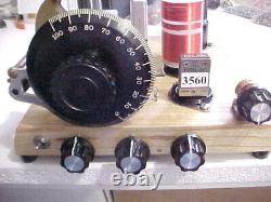
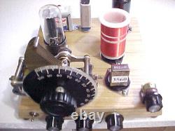
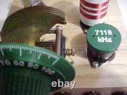
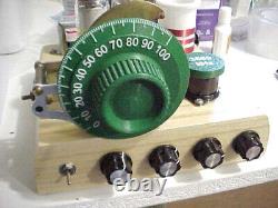
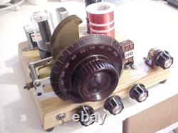
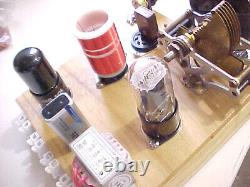
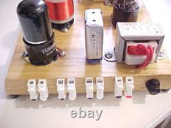
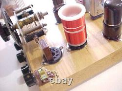
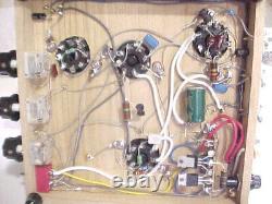
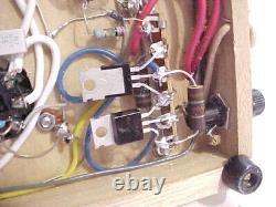


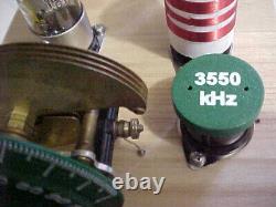
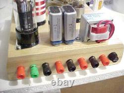


This item has exposed high voltage underneath the chassis. The main tuning dial may vary slightly from radio to radio, depending on what I have in stock. Also, I cannot always find the brass plate variable capacitors, so the radio you receive may be one of the standard gray plate types.
About 80 to 90% of the parts will be either new or nos. A few of the parts will be used, but tested before construction. The circuit has a battery powered dc to ac inverter, and the no load dc voltage underneath the hood is over 300 volts! So even though the power source comes from harmless low voltage batteries it can still be lethal if not handled responsibly.
This is a vacuum tube ham radio QRP cw transmitter and regen radio. The circuit uses a 12A6GT tube for the transmitter and a 12L6 for the receiver detector. In either case, the pin-outs are the same as the 12V6 and 12W6 tubes, so any of these tubes will work with no circuit changes necessary.The 12L6 had a slight edge on the other tubes for volume and regen action response, so that's what I decided to use. The 12A6 tube requires only 0.15 amps drain from the power source and since a 12L6, 12V6 or 12W6 tube requires considerably more amps for the filament and produced only about a 5% gain in power out, I decided to just go with the 12A6 GT for the transmitter. The inverter, which powers only the transmitter tube, turns off instantly when switched to receive mode.
So it is not working at all when in the regenerative receive mode. The chassis requires an external 12 volt power source. I like to use a small motorcycle or golf cart battery, but so much the better if you have an old car battery that you are not using. This powers the filaments and inverter when in transmit mode. On the chassis a 9 volt rechargeable battery is require for the receiver, which is connected in series with the incoming 12 volt source, providing about 20 volts or so to run the regen detector.The receiver requires high impedance 2 to 4k ohm inductive or piezo headphones (not included). You may use a well filtered 12 volt bench supply to run this radio. It should be capable of about 2.5 amps in transmit mode. For this circuit there's only a few ma drain on the 9 volt battery, so it will go for many hours if not days before needing to be recharged.
The QRP transmitter output on 160 and 80 meters is in the 3 to 4 watt range. The output on 40 meters is about 2.4 watts. Power out on these old audio tubes drops off considerably as you go up in frequency. It will likely work okay on 30 meters if you care to make a coil for that band, but power out will likely no more than 1 to 2 watts. I'll provide one each, QRP HC49 crystal types, for 80 and 40 meter cw, but I have no spares for 160 meters. You'll need to supply a crystal for that band. Plug-in coils are provided for the bands mentioned. The receiver coverage is pretty much continuous from about 1600 khz to 12.5 mhz, by changing the coils. The dc inverter circuit employs a pair of TIP41C power transistors, working with a 6-0-6 volt 5 watt transformer that has a secondary winding of 220 volts. The output is then rectified by a 1N4007 diode, then filtered, for well over 300 volts dc, no load.I will include a hand-sketched wiring diagram of this item, plus a sketch of all control panel functions. I guarantee this radio will work if you get everything hooked up properly. The controls are receiver main tuning, fine tuning, receive antenna coupling and regenerative action/power on/off switch. The transmitter has a single control for power out, with link coupling to the antenna.
There's a single send/receive switch which controls all necessary functions, including high voltage power on for transmit and switching the antenna. So you only need a single antenna for send/receive.In send mode the audio output will automatically be muted. AGAIN, EVEN THOUGH POWERED BY BATTERIES, IT CAN BE QUITE LETHAL IF NOT HANDLED WITH RESPECT!
This is a given for most any ham radio transmitter.
